- 您现在的位置:买卖IC网 > Sheet目录311 > AS1113-BSST (ams)IC DRIVER LED 16-CHAN 24-SSOP
AS1113
Datasheet - D e t a i l e d D e s c r i p t i o n
If there are multiple AS1113s in a chain, the error flag will be gated through all devices. To get a valid result at the end
of the chain, a logic 1 must be applied to the SDI input of the first device of the chain. If one device produces an error
this error will show up after n *t P(I/O) + t SW(ERROR) at pin SDO of the last device in the chain. This means it is not possi-
ble to identify which device in the chain produced the error. Therefore, if a global error occurs, the detailed error report
can be run to identify which AS1113, or LED produced the error.
Note: When no error has occurred, the detailed error report can be skipped, setting LD and subsequently OEN low.
Error Detection Functions
Open-LED Detection
The AS1113 open-LED detection is based on the comparison between V DS and V THL . The open LED status is aquired
at the rising edge of OEN and stored internally. While detecting open-LEDs the output port must be turned on. Open
LED detection can be started with 1 clock pulse during error detection mode while the output port is turned on.
Note: LEDs which are turned off at test time cannot be tested and will be shown as a logic 1 in the detailed error
report.
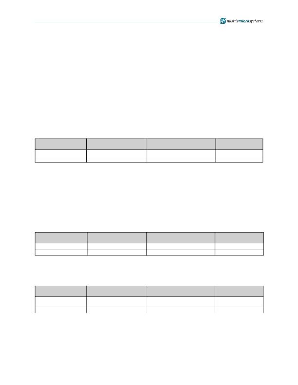
Table 6. Open LED Detection Modes
Output Port State
On
On
Effective Output
Point Conditions
V DS < V THL
V DS > V THL
Detected Open-LED
Error Status Code
0
1
Meaning
Open Circuit
Normal
Shorted-LED
The AS1113 shorted-LED detection is based on the comparison between V DS and V THH . The shortened LED status is
aquired at the rising edge of OEN and stored internally. While detecting shorted-LEDs the output port must be turned
on. Shorted-LED detection can be started with 2 clock pulses during error detection mode while the output port is
turned on.
For valid results, the voltage at OUTN0:OUTN15 must be lower then V THH under low-current diagnostic mode operat-
ing conditions. This can be achieved by reducing the V LED voltage or by adding additional diodes, resistors or LED’s.
Note: LEDs which are turned off at test time cannot be tested and will be shown as a logic 1 in the detailed error
report.
Table 7. Shorted LED Detection Modes
Output Port State
On
On
Effective Output
Point Conditions
V DS > V THH
V DS < V THH
Detected Shorted-LED
Error Status Code
0
1
Meaning
Short Circuit
Normal
Overtemperature
Thermal protection for the AS1113 is provided by continuously monitoring the device’s core temperature. The overtem-
perature status is aquired at the rising edge of OEN and stored internally.
Table 8. Overtemperature Modes
Output Port State
Don’t Care
Don’t Care
Effective Output
Point Conditions
Temperature > T OV1
Temperature < T OV1
Detected Overtemperature
Status Code
0
1
Meaning
Overtemperature
Condition
Normal
www.austriamicrosystems.com/LED-Driver-ICs/AS1113
Revision 1.04
12 - 24
发布紧急采购,3分钟左右您将得到回复。
相关PDF资料
AS1117-BQFT
IC DRIVER 64LED MOBILE 24-TQFN
AS1118-BQFT
IC DRIVER 64LED W/DELAY 24-TQFN
AS1121B-BQFT
IC DRIVER 16-CH 32-TQFN
AS1122B-BQFT
IC LED DVR 12-CH 24-TQFN
AS1123-BTST
IC LED DVR 16-CH 40MA 24-QSOP
AS1390A-ZQFT
IC BOOST CTLR/BUCK CONV 20-QFN
AS212-L
SOCKET 12V AUTO SAFETY CAP MNT
AS212C
AUTO 12V SOCKET W/SAFETY CAP
相关代理商/技术参数
AS1113BSSU
制造商:AMS 功能描述:IC LED DRIVER CONSTANT CURRENT SSOP24 制造商:AMS 功能描述:IC, LED DRIVER, CONSTANT CURRENT, SSOP24 制造商:AMS 功能描述:IC, LED DRIVER, CONSTANT CURRENT, SSOP24; Topology:Constant Current; No. of Outputs:16; Output Current:50mA; Output Voltage:15V; Driver Case Style:SSOP; Input Voltage Min:3V; Input Voltage Max:5.5V; Dimming Control Type:Analogue ;RoHS Compliant: Yes
AS1113-BSSU
功能描述:LED显示驱动器 RoHS:否 制造商:Micrel 数位数量:5 片段数量: 安装风格:SMD/SMT 封装 / 箱体:PLCC-44 工作电源电压:4.75 V to 11 V 最大电源电流:10 mA 最大工作温度:+ 85 C 最小工作温度:- 40 C 封装:Tube
AS1113CVB
功能描述:AS1113 - Power Management, Power Over Ethernet (POE) Evaluation Board 制造商:akros silicon 系列:- 零件状态:停产 主要用途:电源管理,以太网供电(POE) 嵌入式:- 使用的 IC/零件:AS1113 主要属性:- 辅助属性:过压,热和欠压保护 所含物品:板 标准包装:1
AS1113-XXX-I-A1-D
制造商:未知厂家 制造商全称:未知厂家 功能描述:Analog Filter
AS1113-XXX-I-A1-S
制造商:未知厂家 制造商全称:未知厂家 功能描述:Analog Filter
AS1113-XXX-I-A2-D
制造商:未知厂家 制造商全称:未知厂家 功能描述:Analog Filter
AS1113-XXX-I-A2-S
制造商:未知厂家 制造商全称:未知厂家 功能描述:Analog Filter
AS1113-XXX-I-A3-D
制造商:未知厂家 制造商全称:未知厂家 功能描述:Analog Filter
